Logic synthesis is the process of converting the behaviour of design written in any hardware description language such as VHDL, Verilog into an optimised gate-level netlist mapped to the specific technology library.
The above figure describes the Synopsys Design compiler flow for logic synthesis and different input files to the design compiler with the back-annotation to perform physical aware or timing aware synthesis.
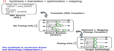
The steps which are followed in Logic synthesis are as follows:
1. Translation: In this step, HDL is checked for syntax errors and converted into a technology-independent gate-level netlist. The converted code is a functional equivalent boolean expression.
2. Optimization: The main objective of this step to increase the efficiency of the design by replacing some part of the gates with another that can perform the same task faster. Hence, the converted gate-level netlist is optimised using different optimisation techniques like logic restructuring etc.
3. Mapping: In this step, the gate-level netlist is mapped with a technology-dependent logic gate based on design constraints and target library. The output will be optimised technology-specific gate-level netlist in Verilog.
There are two different types of constraints that are applicable to design that are:
1. Design rule constraints: These constraints are provided by the foundry in .lib format. These constraints are required for a design to
function correctly. They apply to any design that uses the library. By default, the design rule
constraints have a higher priority than optimisation constraints. for example,
a) Maximum transition: This constraint will define the maximum time for the net at which its driving cell will change its logic value. It is set by using the command set_max_transition.
b) Maximum fanout: It is the maximum fanout limit at any driving pin, and the tool will check for it. It is set by command set_max_fanout.
In the above figure, we have a fanout of 10 at a driving pin X. In such case, the tool will compare as:
10 > 2 +2+2+1
for this case, it meets our critical condition, but if it fails to do so, the tool will replace this cell with some other cell having a higher fanout driving capacity.
c) Maximum capacitance: The pin-level attribute specifies the maximum capacitive load that output can drive. The tool calculates capacitances on the net by adding all the wire capacitances and the capacitances of pins connected to that net. It is set by command set_max_capacitances.
Fig. Default design rule attributes given in .lib
Fig. Attributes related to a cell.
2. Optimization rule constraints: These constraints define the speed, area, and power design goals that the designer decides to achieve optimum results. These constraints will act as maximum cost functions, which the tool has to minimise.
The optimisation constraints consist of :
1. Timing constraints (speed and performance): For specifying timing constraints, we need to check the path first on which design is working. It can have an asynchronous or synchronous path.
In the synchronous path, we need to define the clock. It can be set by using the create_clock command. After that, we can determine the maximum and minimum delay of a path using set_min_delay and set_max_delay commands. The tool will optimise the path by using different cells to get a lower value than the value set using the above commands.
We can define the maximum and minimum delay of a path from one point to another using set_min_delay and set_max_delay commands in the asynchronous path.
2. Area constraints (maximum no. of gates): Maximum area represents the number of gates in the design, not the physical area the design occupies. Usually, the area requirements for the design are stated as the most minor design that meets the performance goal. It is set by command set_max_area.
3. Power constraints: The power requirements of the design are stated as the design that can meet power goals specified by a command like set_max_power, which defines the total power, set_max_leakage_power. This command defines the maximum leakage power that our design can handle and set_max_dynamic power to set the maximum dynamic power of the design.
In the next article, we will discuss different optimization rule constraint and how we can specify this information to the tool for better results.
Thank you for reading this article.
Feel free to reach me at:
E-mail id: hemantjuneja710@gmail.com
LinkedIn: https://www.linkedin.com/in/hemant-juneja-84aa6313b/
Please comment down your suggestions, Happy learning :)
References :
1. http://www.vlsiexpert.com/2012/02/designconstraintmaximumtranstion.html#:~:text=So%20Costraints%20are%20the%20instructions,or%20how%20the%20tool%20behaves.
2. http://smdpc2sd.gov.in/downloads/IEP/IEP%208/24-02-18%20Rejender%20pratap.pdf
3. https://www.eng.auburn.edu/~nelson/courses/elec5250_6250/slides/LogicSynthesis-Synopsys.pdf